|
|
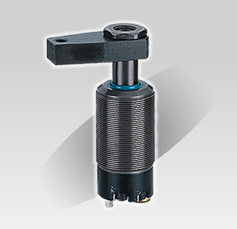
High Pressure Swing Cylinder
- This type of hydraulic cylinder is suitable for use when unobsructed space muct be maintained along the path of the clamped workpiece and high-pressure clamping and convenientmovement of the workpice is required.
- This hydraulic cylinder clamps on the downstrocke.Its movement includes a rotation stroke (please do not clamp workpice during this stroke) and a vertical downstroke.
- Employs German oil seals and other imported parts. To insure high performance and a long servicelife, the bor has been subjected to special treatment.
- Please consult performance data to determine maximum oil filling rate. To avoid an excessive rotation speed, do not use too high an oil filling rate . If rotation is not correct, ues a flow control valve to reduce the filling rate.
|
|
Specifications
 |
HPS-25 |
HPS-40 |
| Bore Size (mm) |
Ø25 |
Ø40 |
| Rod Size (mm) |
Ø20 |
Ø32 |
| Swing Stroke (mm) |
7 |
8 |
| Clamp Stroke (mm) |
11 |
14 |
| Swing Direction |
Right or Left |
| Swing Degrees |
Standard 90° |
| Min. Operation Pressure |
30kg/cm
² |
| Maximum oil filling rate (cc/s) |
3.2 |
10 |
Oil volume needed for
down stroke (cc) |
3.2 |
10 |
Oil volume needed for
reture stroke(cc) |
8.8 |
27.7 |
|
|
Relationship of effective clamping strength (Fsp) to working pressure (p) |
 |
|
 |
|
Single - Acting
|
|
Double - Acting
|
|
How To Place Order
 |
HPS Series |
 |
Bore Size Ø25, Ø40 |
 |
Operation - S:Single-Acting, D:Double-Action |
 |
A: Threaded Type, B: Flange Type |
 |
Swing Direction R or L |
 |
Swing Degrees 90° |
|
|
Dimensional Table
Unit:mm
 |
HPS-25 |
HPS-40 |
| A1 |
105.5 |
119.5 |
| A2 |
126.5 |
147.5 |
| B |
84.5 |
94.5 |
| C |
8 |
8 |
| D1 |
M45x1.5 |
M60x1.5 |
| D2 |
Ø43 |
Ø58 |
| E1 |
M18x1.5 |
M28x1.5 |
| E2 |
Ø23.5 |
Ø33.5 |
| E3 |
30 |
40 |
| E4 |
9 |
10 |
| F1 |
65 |
85 |
| F2 |
45 |
63 |
| G1 |
50 |
65 |
| G2 |
30 |
44 |
| H |
Ø6.5 |
Ø8.5 |
| I |
12 |
12.5 |
| J |
12 |
19.5 |
| K |
15 |
28 |
| O |
S8 |
S8 |
|